Electric fence in hazardous areas: explosion-proof checklist
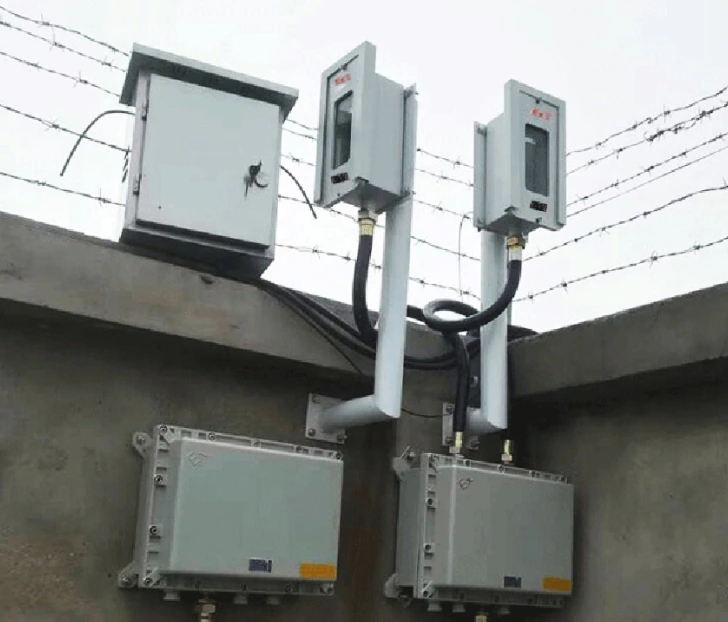
Zone 1 and Zone 2 checks cover Ex d IIB T6 Gb / Ex ib IIC T6 devices, 2–4 beam barriers at 30–250 m, and 80–150 m zones. Before handover, verify 8 documents: area drawing, Ex certificates, cable entries, bonding, test records, settings, maintenance procedure and as-built zone map.
In a hazardous area, the product catalogue is the last document you should open. The first is the area classification drawing. It tells you which zone applies, which gas group and which temperature class — and therefore which Ex code is acceptable.
This checklist is written for perimeter and area detection around tank farms, loading terminals and chemical plants. It is a project aid, not a certification opinion; the authority having jurisdiction and the site’s safety engineer make the final call.
What does the area drawing tell you?
Read three things: the zone (0, 1 or 2), the gas group (IIA, IIB or IIC) and the temperature class (T1–T6). Zone 0 is inside the tank or pipe; Zone 1 is where a release is likely in normal operation; Zone 2 is where a release is possible but unlikely. The detector’s Ex code must be equal to or better than the area requirement.
Also read the drawing’s notes: ventilation, drainage, dyke height and the extent of the classified envelope. A detector mounted two metres outside the line on paper may be inside the actual gas cloud on a still night.
Which Ex code do you actually need?
The catalogue family covers several codes: Ex d IIB T6 Gb for flameproof infrared barriers and detectors, Ex d IIC T6 Gb for alarm sounders, Ex ib IIC T6 for intrinsically safe vibration detectors, and DIP A20 Ta T6 for dust. The code must match the drawing, not the marketing preference.
“Gb” is the equipment protection level; it is not decoration. A device marked Gc is not a drop-in replacement for a Gb device in the same zone. Check the full marking on the nameplate, including the ambient temperature range.
| Device | Typical marking | Use |
|---|---|---|
| Infrared barrier | Ex d IIB T6 Gb | Perimeter line, wall or fence |
| Alarm sounder | Ex d IIC T6 Gb / DIP A20 | Local audible/visual alarm |
| Vibration detector | Ex ib IIC T6 | Tank shell, fence fabric, door |
| Gas detector | Ex d IIC T6 Gb, IP65 | Pump seal, loading point |
Can you use a standard fence host nearby?
Only outside the classified area and subject to the ignition-risk assessment. The host is electrical equipment with a high-voltage output; it does not belong inside Zone 1 or Zone 2 unless it is itself Ex-rated. Place it in the control room or a non-classified enclosure, and run the high-voltage lead through a protected route.
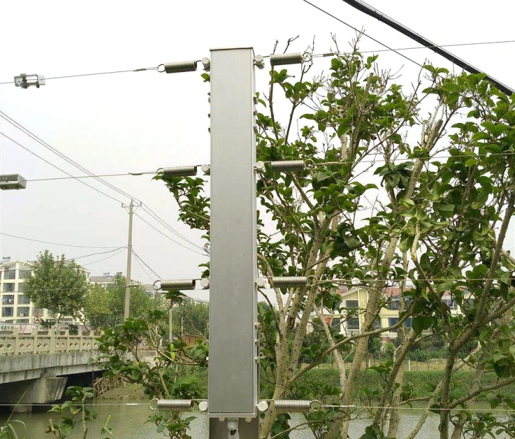
If the fence itself must enter the hazardous area, use an Ex-rated sensor or a non-electrical layer such as tension or fibre. The fence wire can be inside the zone while the host stays outside; the boundary of the electrical circuit is what matters.
How do you install cable entries and bonding?
Use the cable entry specified on the Ex certificate: a certified gland, the correct thread (often G3/4 or M20), and a sealing washer. An uncertified entry voids the protection. Leave no unused holes open; fit certified blanks.
Bond every metal enclosure to the site’s equipotential system with the conductor size required by the installation drawing. Do not use the cable shield as the only bond. Record the bonding resistance in the handover file.
What maintenance is allowed in the zone?
Visual inspection, cleaning the window with a damp cloth, and replacement of parts explicitly permitted by the manual. Opening a flameproof enclosure or disconnecting an intrinsically safe circuit normally requires a gas-free permit and isolation. Follow the site’s permit-to-work system; do not improvise.
Keep the flameproof joint clean and unpainted. A painted joint can trap solvent and change the gap; a filed joint is no longer certified. If a cover is damaged, replace it with the manufacturer’s part, not a locally fabricated one.
What documents belong in the handover pack?
Ex certificates for every model, the nameplate marking photo, the area drawing with device locations, the installation and maintenance manual, cable entry and bonding records, gas detector calibration records, and the earth resistance test.
Also include the response procedure: who is called, what is isolated, and what is not touched. In a hazardous area, an unclear response can turn a small alarm into a safety incident.