Electric fence energizer sizing: voltage, joules and backup power
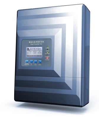
For a 500 m wall with 5 zones, specify a host with 5 channels, 3–10 kV output and at least 8 h backup; a 2 km mesh line may need 2–3 zone hosts or repeaters. Joules decide the shock, voltage decides the reach, and pulse interval (1–1.5 s) decides the load cycle.
An electric fence energizer is usually sold on one headline number: output voltage. That number matters, but it does not tell you how much work the pulse can do, how long it lasts, or how the fence will behave at the far end of a long, wet zone. Sizing starts by separating those questions.
This guide explains how voltage, stored joules and pulse width interact, how to set zone length by fence type, and how to plan 12 V backup so a battery electric fence stays armed through a mains failure. Figures come from the published pulse family: 3–10 kV, ≤2.5 J and one pulse per second.
What is the difference between voltage and joules?
Voltage is potential difference: it decides whether a pulse can cross a dirty insulator, a wet leaf or a small air gap. Stored energy is the work the capacitor can deliver, measured in joules. A high-voltage pulse with little energy can arc and sting, but it cannot push a long, leaky circuit. A lower-voltage pulse with more joules may hold its voltage farther down the wire.
The two numbers answer different design questions. Voltage sets clearance to other metal, insulator rating and arcing risk. Energy sets how much wire, vegetation and leakage the energizer can drive while still leaving a detectable pulse at the last post. Two energizers labelled 10 kV can behave very differently on the same 300 m wall.
How do you read an energizer datasheet?
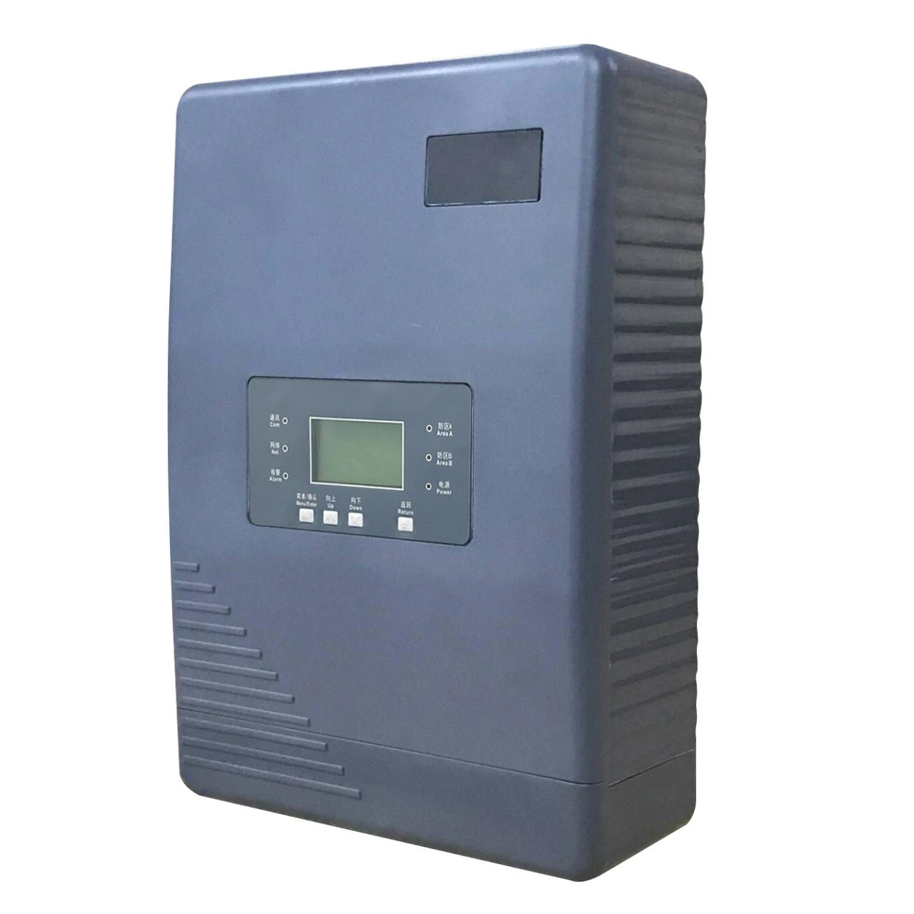
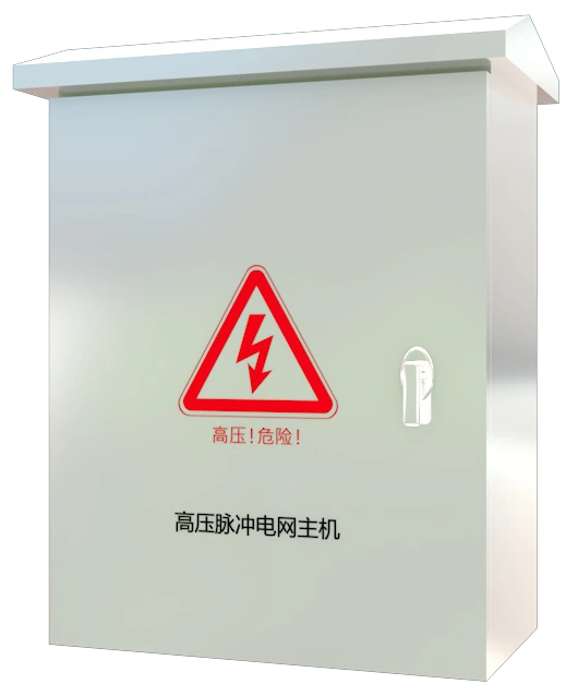
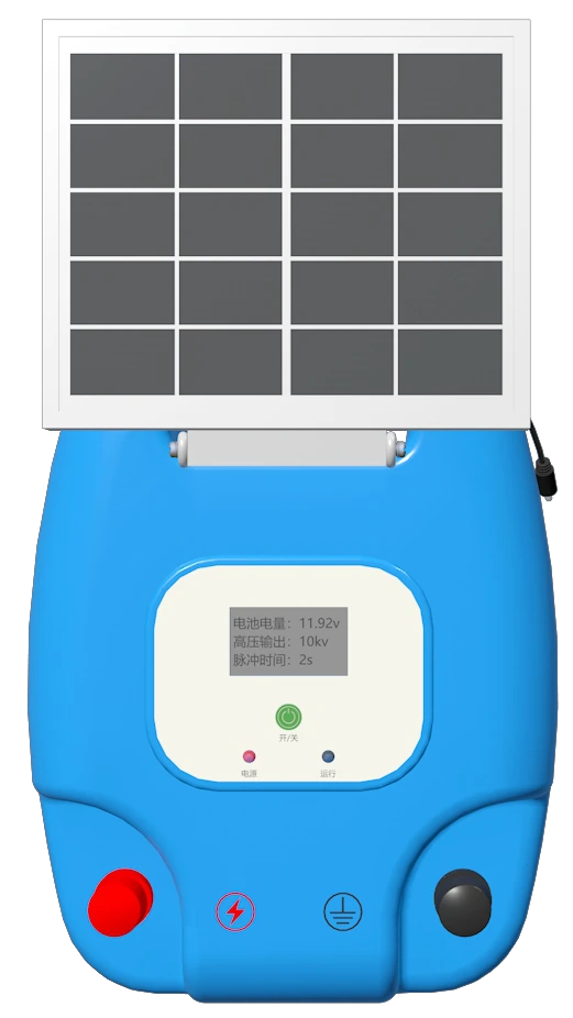
A pulse energizer datasheet lists output voltage, energy per pulse, pulse duration, peak current and pulse interval. The perimeter family is published at 3–10 kV, ≤2.5 J per pulse, ≤0.1 s pulse duration, ≤10 A peak current and a 1 s interval. Some models add a 600–1,500 V low-voltage mode for testing.
These values move together. For a fixed capacitor, a higher voltage means a shorter or lower-current discharge. A longer pulse delivers more energy for the same voltage. A livestock energizer shows the trade: 8–12 kV, 1.5–3 J and a 100 µs pulse, with a 1 s or 1.5 s interval. The principle is identical; the balance differs.
| Parameter | Typical figure | What it decides | Practical meaning |
|---|---|---|---|
| Output voltage | 3–10 kV; 600–1,500 V low-voltage mode | Ability to cross gaps and insulation | Higher voltage needs more clearance, not more energy. |
| Stored energy | ≤2.5 J per pulse | Work available for the fence circuit | Energy drives a long, leaky zone; voltage alone cannot. |
| Pulse width | ≤0.1 s | How long energy is delivered | Short pulses limit shock duration but still require isolation. |
| Pulse interval | 1 s (1–3 s adjustable on X5) | How often the circuit is tested | Fast detection without continuous voltage on the wire. |
| Peak current | ≤10 A | Current into a short circuit | A short is a strong event; output is limited. |
What a zone loads onto the energizer
A fence is a circuit, not a cable. Every metre of alloy wire adds resistance, and every joint, insulator, wet leaf and grass stem adds leakage. The energizer spends its stored energy charging the whole circuit, so the voltage at the far end is always lower than at the terminal. Eight kilovolts at the host can become four at the last post.
Load is dynamic. Dry soil, clean insulators and short grass are a light load; rain, salt spray, overgrown vegetation and a cracked insulator are heavy. Size for the heavy condition, not commissioning day. If vegetation touches the wires, no energizer setting can compensate for a permanent leakage path.
How do you size an energizer by fence type?
Zone length is a response decision first and an electrical decision second. On a wall, 100–300 m per zone is a practical planning range. On mesh, 80–200 m is typical. On a long open line with vehicle patrol, 200–400 m can work when far-end voltage and the response route are both verified. These are planning ranges, not ratings.
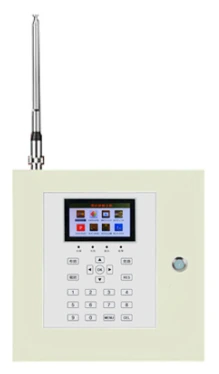
Match the host class to the zone, not the site’s total length. A single- or dual-zone pulse energizer suits a wall or a pair of short returns. A long boundary is normally several zones on an RS485 or network bus. The control layer carries the 1–128 addresses; one energizer should not drive the whole perimeter.
| Fence type | Typical zone | Host class | Wires and posts | Watch-outs |
|---|---|---|---|---|
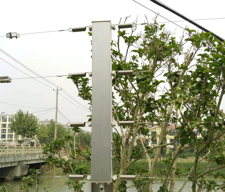
| Masonry or concrete wall, wall-top | 100–300 m | Single- or dual-zone pulse energizer | 4 wires; terminal posts ≤100 m, intermediate 4–5 m | Wall condition; 30 mm clearance; public reach and signage |
| Mesh or chain-link fence | 80–200 m | Dual-zone pulse energizer | 4 or 6 wires; terminal posts at corners | Flex and vegetation; earth return; gate breaks |
| Long open boundary with vehicle patrol | 200–400 m | Multi-zone hosts on RS485 or network | 6 wires; terminal posts ≤100 m | Far-end voltage; repeaters; response time |
| Livestock pasture or orchard | 1–3 or 3–10 km single wire, model dependent | Livestock energizer class | Single wire or tape; earth rods | Vegetation load; earthing; solar sizing |
How many zones can one energizer host support?
A dual-zone host is not two energizers in one box. It is one energizer that can drive two separate runs, with each zone set at the panel. That suits a wall split by a gate or two short returns. It is not a way to halve the cable: if both runs are long and wet, the same stored energy serves both.
For a long perimeter, use several hosts on an RS485 bus or the network, each with its own zone address. The bus supports addresses 1–128, but the practical count is set by cable length and response. A multi-zone arrangement also localises faults: one host and one zone, not the entire boundary.
How long does a 12 V battery backup last?
A battery electric fence is the same pulse circuit without mains. The host is supplied from DC18–24 V and accepts a 12 V backup battery input. Published standby figures are 8–24 hours, depending on battery capacity and the number of hosts on the circuit. That is a range, not a guarantee.
Size the battery from the local outage pattern and measured load. Record host consumption (≤15 W for the pulse family), the number of hosts and the hours required, then confirm battery capacity with the supplier. For a livestock fence beyond mains, the solar energizer makes the same decision: panel, battery and load matched to the worst month.
Which installation details change output?
No energizer compensates for a poor earth. Each zone needs high-voltage arresters bonded to a dedicated electrode, with a target below 10 Ω, and the fence earth should not be casually bonded to the building lightning protection. Keep alloy wires 30 mm from other metal, 200 mm from plants, and fit warning signs every 10 m.
Run power and RS485 in separate conduits, daisy-chain the bus and keep the high-voltage lead away from communication cable. Enclosure ratings matter too: IP55 suits many outdoor control positions where stated, but the exact model manual remains the authority. Coastal and dusty sites need earlier inspection.
What is a practical energizer sizing sequence?
Start with the fence line, not the catalogue. Measure the actual wire length per zone, count the wires and note wet areas, vegetation and joints. Set zone boundaries at corners and gates a guard can reach. Only then choose the energizer class, zone count and backup.
Commission with measurements: record the voltage at the host and at the farthest post of every zone, in dry and wet conditions where possible, and log battery voltage during a mains-off test. An unmeasured sizing decision is only a guess with a datasheet attached.