
Electric fence energizer system
5,000–10,000 V bi-polar pulse, one pulse per second, ≤2.5 J.
- Series / models
- X3 / X5 / X6 series
- Detection
- Bi-polar high-voltage pulse on alloy wires
- Typical range
- Up to 100 m per terminal span; zone length by layout
- Control
- RS485 / network / dry contacts
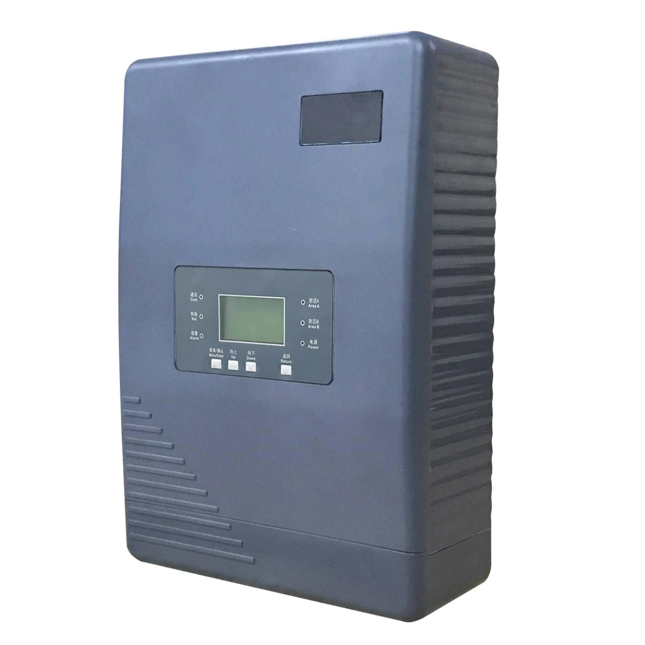
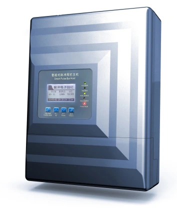

Electric fence energizer system
| Output | 5–10 kV pulse |
|---|---|
| Wires | 4 or 6 |
| Zones | 1 or 2 |
| Interface | RS485 + RJ45 |
5,000–10,000 V bi-polar pulse, one pulse per second, ≤2.5 J.
Bi-polar pulse
Every wire carries a pulse and adjacent wires sit at different potentials, so a bridge between two wires is detected as a short circuit.
Four alarm classes
Open circuit, short circuit, enclosure tamper and power loss are reported separately, which shortens the diagnosis on site.
Single or dual zone
One host can protect one continuous run or two separate runs, with the zone number set from the front panel.
RS485 and RJ45
The host connects to a control keyboard, K-series alarm host or the management platform over RS485 or the built-in network port.
Battery backup
A 12 V DC battery input keeps the fence armed through a mains failure; the panel reports the power-loss event.
Lightning path
High-voltage arresters are fitted at the terminal posts and bonded to a dedicated earth electrode below 10 Ω.
From principle to site
Values are typical manufacturer data. Site conditions, power supply and configuration can change the final specification.
How the fence decides that a climb is a climb
The host sends a short high-voltage pulse along the alloy wires once per second. When a person bridges two wires, cuts a wire or opens the wiring panel, the electrical characteristic of the loop changes and the host reports the event within the same pulse cycle. The front panel separates open circuit, short circuit, tamper and power loss so the guard knows whether to inspect a cut, a climb or a hardware fault.
Because adjacent wires are at different potentials, a jumper placed across two wires does not silence the zone — it creates a short. That is the practical difference between a bi-polar fence and a single-polarity deterrent that only reacts to a complete cut.
Zone planning, post spacing and price per metre
Terminal posts are placed at the ends of each zone and at corners, with a maximum span of 100 m between terminal posts. Bearing posts are used every 20–25 m and intermediate posts every 4–5 m. Because electric fence wire, insulators, tensioners and posts are priced by the metre, the post layout sets both the electric fence installation time and the electric fence price per metre. A zone should follow one geometric edge of the site; splitting a long straight run into two zones reduces the distance a guard must walk to confirm an alarm.
Keep alloy wires at least 30 mm from other metal surfaces. A closer gap can arc, damage the host and create a false alarm. Warning signs are fixed every 10 m in a visible position, and the fence is not installed during a thunderstorm or on a live circuit.
Run power and RS485 in separate conduits. The communication cable should be a twisted-pair shielded cable (RVSP) and the RS485 bus is daisy-chained, not star-wired. The high-voltage lead and the communication lead must not share a conduit.
Technical specifications
Values are typical manufacturer data. Site conditions, power supply and configuration can change the final specification.
| Model range | X3 / X5 / X6 series |
|---|---|
| Zones | Single or dual zone; 4-wire or 6-wire |
| High-voltage pulse | 5,000–10,000 V (model dependent) |
| Low-voltage pulse | 600–1,500 V |
| Pulse period | 1 s (1–3 s adjustable on X5) |
| Pulse duration | ≤ 0.1 s |
| Peak pulse current | ≤ 10 A |
| Maximum pulse energy | ≤ 2.5 mC |
| Display | 3.0 in (X3 / X5); 3.5 in (X6) |
| Communication | RS485 and RJ45 network |
| Zone address | 1–128 on a shared bus |
| Power supply | DC18–24 V; 12 V backup battery input |
| Consumption | ≤ 15 W |
| Alarm types | Open circuit, short circuit, touch (some models), tamper (some models), power loss, fault |
| Alarm output | Dry NO/NC relay; DC12 V siren output |
| Operating temperature | −40 °C to +50 °C |
| Dimensions | 345 × 242 × 100 mm (X3 / X6); 345 × 265 × 95 mm (X5) |
Where this system is usually specified
Electric fence for homes & villas
A perimeter that a resident can live beside and a guard can actually reach.
View detailsElectric fence for warehouses & factories
Long perimeters, vehicle yards and the places a fence quietly stops working.
View detailsPower & water utilities
Unattended sites where the alarm must be true the first time.
View detailsElectric fence for prisons & correctional facilities
Layers that assume the first one will be tested.
View detailsBuyer questions
Does the pulse injure a person who touches the fence?
The output is a short-duration pulse with limited energy (≤ 2.5 mC and ≤ 10 A peak), designed to deter rather than injure. It is still a high-voltage circuit: warning signs, a visible fence line and an isolation procedure for maintenance are mandatory, and the host must be installed out of reach.
Can it report to an existing CCTV or alarm system?
Yes. Each host provides dry NO/NC relay contacts and a 12 V siren output. RS485 and the built-in network port carry zone status to a K-series control host or the management platform, which can then trigger cameras and maps.
How long does the fence stay armed during a power failure?
The host accepts a 12 V DC backup battery. Published standby figures range from 8 to 24 hours depending on battery capacity and the number of hosts on the circuit; size the battery for the local outage pattern rather than the brochure figure.
How many hosts can share one RS485 bus?
Zone addresses can be set from 1 to 128 on the bus. In practice the bus length, cable quality and the number of repeaters limit the installation; keep each RS485 segment within the cable manufacturer’s length limit and use a repeater for long perimeters.
Systems that work alongside it
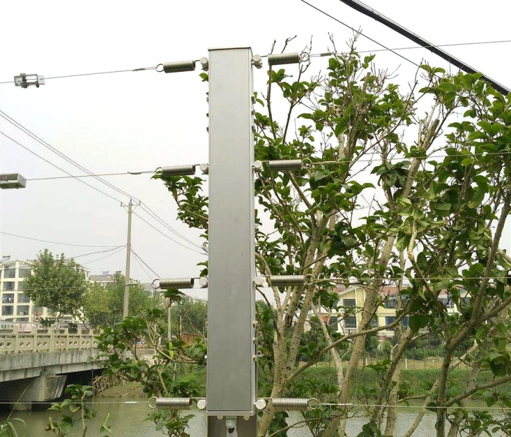
Tension fence
Fence detection · S7W / S9 / X800 / X900
Detects climbing, cutting and slackening without voltage on the fence.
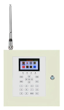
Electric fence alarm & control
Electric fence alarm · K7 / K9 / K10 hosts · touch terminal · management software
Arm, map and verify every electric fence zone from one interface.
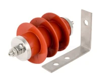
Electric fence wire & accessories
Electric fence accessories · Posts, insulators, alloy wire, tensioners, grounding
Electric fence wire, insulators and tensioners — the parts that decide year five.
Specify this system for your perimeter
Send the perimeter length, fence or wall type and the response requirement. We will return a zone plan and a configuration.